Công ty cổ phần công nghệ và tư vấn CIC
Specialized
Home > News > Specialized > Bored Pile Ultrasonic Testing – Determining First Arrival Time (FAT) and Wave Speed
Construction Robots and Their Practical Value for Modern Construction Sites

KOMPAS-3D V24 Launches with Major Upgrades for Mechanical Design
5 Principles for Effective BIM Implementation in Vietnam
OpenFlows Water & Sewer 2026 – Bentley’s Powerful Software Duo

enjiCAD 2027 Officially Launched with Breakthrough Performance and an Enhanced Design Experience...
Nội dung chính
Bored Pile Ultrasonic Testing – Determining First Arrival Time (FAT) and Wave Speed
26/06/2026
Lượt xem 4
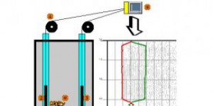
If we remove all supporting features—which are intended to make our work faster and easier—and reduce a bored pile ultrasonic testing system to its most fundamental principle, the heart of the system is simply a timer: it transmits a pulse one side and measures the time required for the pulse to reach the other side.
The waves travelling through the tested structure—the bored pile—are reflected its boundaries, attenuated and subjected to constructive or destructive interference. We are only interested in the arrival time of the first wave, which follows the fastest path and provides the most clearly defined measurement. This is known as the First Arrival Time (FAT).
Noise and FAT
In the absence of noise, FAT could be identified as the moment when the signal first becomes non-zero. However, noise is an unavoidable part of any physical measurement, and determining the actual wave arrival time is not a simple task. When noise is present, identifying FAT is no longer entirely objective, and the human eye is still considered the most effective tool for selecting the FAT point.
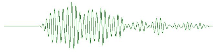
Clean pulse without noticeable noise
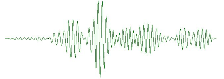
Pulse with typical noise
Sources of Noise
Noise originates both external and internal sources:
-
External: Ambient environmental noise, probes rubbing against the walls of the access tubes and other sources generate sound waves that mix with the actual signal in unpredictable ways.
-
Internal: Every electronic system contains inherent noise. This is the voltage ripple that is always present and ultimately enters the measurement through the analogue-to-digital converter circuit.
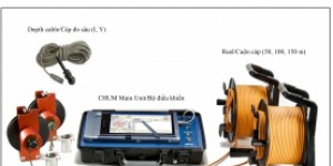
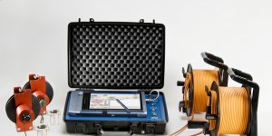
In ultrasonic systems, the transmitter voltage is commonly increased to more than 1 kV, while the receiver voltage is generally measured in millivolts, which is significantly lower. Voltage leakage the transmitter into the receiver circuit is known as crosstalk. Modern systems such as the CHUM equipment use specialised measures to prevent this crosstalk phenomenon.
.png)
Signal affected by crosstalk
FAT Determination Algorithms
A typical pile test can easily generate several thousand wave signals. Manually identifying FAT by visually examining such a large volume of data is repetitive and tiring, making the process highly susceptible to errors. The need for a computer algorithm to perform most—or all—of this demanding work is therefore clear.
The CHUM software provides four different algorithms. Among them, the Automatic algorithm is the most advanced and is recommended for use.
Wave Speed Calculation
Note: “Wave speed” is a more accurate term than “velocity” because speed is a scalar quantity with no direction, whereas velocity is a vector quantity and must always be associated with the direction of the wave.
Apparent wave speed is always calculated using the following formula:
.png)
Because the wave path is not always perfectly straight, the actual distance travelled may be greater than the distance between the two access tubes. In addition, the concrete through which the wave travels is not a homogeneous material. Therefore, the calculated wave speed is an apparent wave speed rather than a directly measured physical property. Wave speed is an indicator of the compressive strength of concrete.
The CHUM software provides two wave speed calculation modes:
-
Simple calculation: Directly uses the entered distance between the two access tubes and the selected FAT point.
-
Advanced calculation: When the access tube diameter, sensor probe diameter and wave speed in water are known, the software can compensate for the time and distance travelled by the wave through the water.
-
The distance is reduced to represent only the wave path through the concrete by subtracting the portion travelled through the water inside the access tubes.
-
FAT is reduced to compensate for the time the signal travelled through the water, assuming a constant wave speed in water of 1,500 m/s.
-
The difference between these two calculation methods can become significant when the distance between the access tubes is small. This calculation method is a supplementary result obtained a conventional bored pile ultrasonic test. The CHUM software also includes a dedicated utility for measuring wave speed with greater accuracy. Please refer to the Wave Speed Calculator.
.png)
Conclusion
Ultrasonic testing of bored pile uniformity is the fastest and most accurate method for assessing defects in concrete piles. With accurate parameters, engineers can:
-
Perform quality control and quality assurance activities for large-diameter concrete piles.
-
Conduct advanced analyses to accurately determine the position and shape of any defects occurring within the pile.
For further information, please contact:
Software Solutions and Technology Equipment Centre – CIC Construction Technology and Consultancy Joint Stock Company
Hotline: 0976 268 036 / 024 3974 1373